


Review of R, X, and Z
Before we begin to explore the effects of resistors, inductors, and capacitors connected together in the same AC circuits, let's briefly review some basic terms and facts.
Resistance is essentially friction against the motion of electrons. It is present in all conductors to some extent (except superconductors!), most notably in resistors. When alternating current goes through a resistance, a voltage drop is produced that is in-phase with the current. Resistance is mathematically symbolized by the letter "R" and is measured in the unit of ohms (W).
Reactance is essentially inertia against the motion of electrons. It is present anywhere electric or magnetic fields are developed in proportion to applied voltage or current, respectively; but most notably in capacitors and inductors. When alternating current goes through a pure reactance, a voltage drop is produced that is 90o out of phase with the current. Reactance is mathematically symbolized by the letter "X" and is measured in the unit of ohms (W).
Impedance is a comprehensive expression of any and all forms of opposition to electron flow, including both resistance and reactance. It is present in all circuits, and in all components. When alternating current goes through an impedance, a voltage drop is produced that is somewhere between 0o and 90o out of phase with the current. Impedance is mathematically symbolized by the letter "Z" and is measured in the unit of ohms (W), in complex form.
Perfect resistors possess resistance, but not reactance. Perfect inductors and perfect capacitors possess reactance but no resistance. All components possess impedance, and because of this universal quality, it makes sense to translate all component values (resistance, inductance, capacitance) into common terms of impedance as the first step in analyzing an AC circuit.
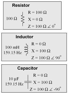
The impedance phase angle for any component is the phase shift between voltage across that component and current through that component. For a perfect resistor, the voltage drop and current are always in phase with each other, and so the impedance angle of a resistor is said to be 0o. For an perfect inductor, voltage drop always leads current by 90o, and so an inductor's impedance phase angle is said to be +90o. For a perfect capacitor, voltage drop always lags current by 90o, and so a capacitor's impedance phase angle is said to be -90o.
Impedances in AC behave analogously to resistances in DC circuits: they add in series, and they diminish in parallel. A revised version of Ohm's Law, based on impedance rather than resistance, looks like this:
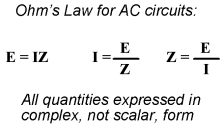
Kirchhoff's Laws and all network analysis methods and theorems are true for AC circuits as well, so long as quantities are represented in complex rather than scalar form. While this qualified equivalence may be arithmetically challenging, it is conceptually simple and elegant. The only real difference between DC and AC circuit calculations is in regard to power. Because reactance doesn't dissipate power as resistance does, the concept of power in AC circuits is radically different from that of DC circuits. More on this subject in a later chapter!


No comments:
Post a Comment